The user inteface and data input with Fespa IS structural software
The user interface of Fespa IS
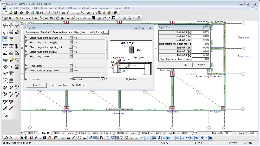
The data input with Fespa IS is accomplished by inserting columns and walls at the positions, defined by the guide lines. Slabs are described the same way. The insertion of beams completes the structural model.
In Fespa IS, the structural model is composed of various entities such as beams, columns, slabs, footings, etc. There is no limit on size and shape.
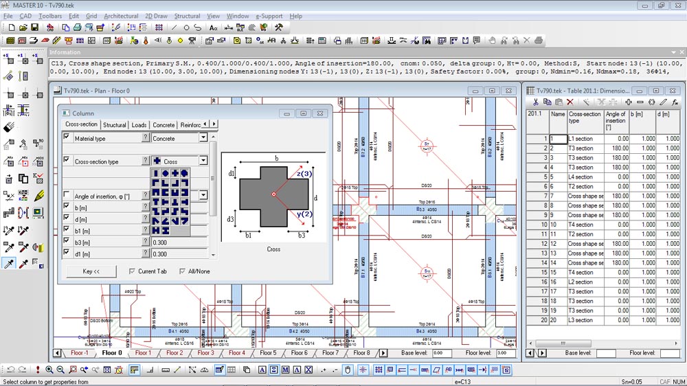
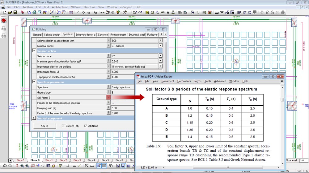
Each entity has its own group of «Properties», which are categorized in appropriate tabs according to their use. For example there are properties
- for geometrical representation in 2D and 3D,
- those for structural analysis and design,
- type and diameter of reinforcement,
- material selection,
- earthquake resistance, etc.
All these properties can be interchanged between the elements of the same entity, thus facilitating the modifications procedure.
Each entity also has its own group of «Commands». They are used for inserting and editing entities. In the prompt bar, constant help guides you through the commands of Fespa IS.
Data input with Fespa IS
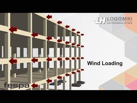
Fespa IS is specially developed for the analysis and design of earthquake resistant structures. All the necessary data is inserted during the geometry description, in plan view. Fespa IS automatically builds the 3D model with all the information required (i.e. continuity of beams and columns) to perform the earthquake analysis by just clicking on the «Analysis and Design» command. No additional data needs to be given at intermediate stages. A few highlights are:
- Automatic calculation of beams” rigid offset length and geometry.
- Automatic calculation of capacity design of beams and columns in shear
- Automatic generation of seismic combinations according to the user’s preferences.
- Soft storey checks according to Indian Standards.
- Automatic calculation of seismic storey drift and displacement.
Various loading conditions can be applied to the entities through the relevant tab in the properties window and the special loading commands.
Guide lines and snap points make the accurate geometry description of even the most complicated structural models really simple. All the given data is automatically transferred in data tables for further assessment and/or quick group changes.
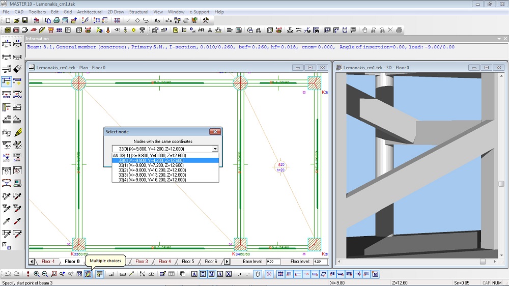
The «multiple choices» command is available and gives the option to choose among nodes or members that have the same position on plan but with different heights.
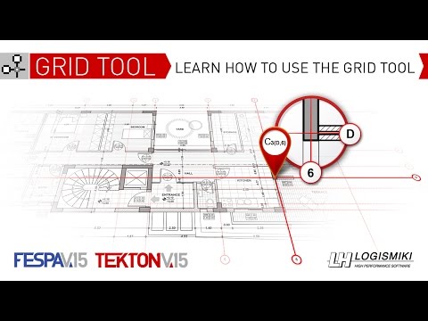
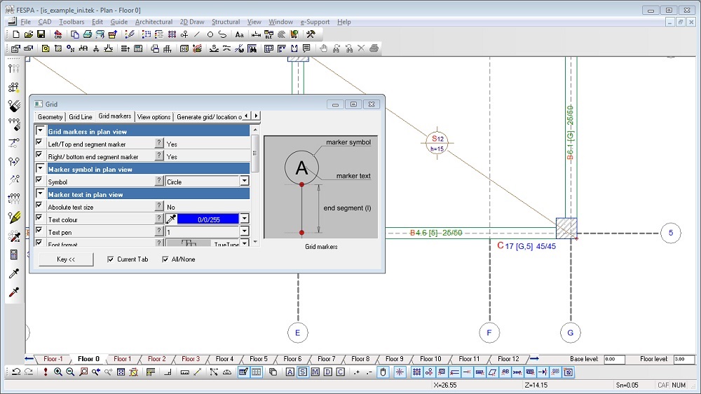
Active grid tool/ automatic assignment of location to all members
Fespa IS is equipped with an intelligent user friendly active grid tool that assigns automatically to all beams, columns and footings their location name within the project at both plans and elevations.
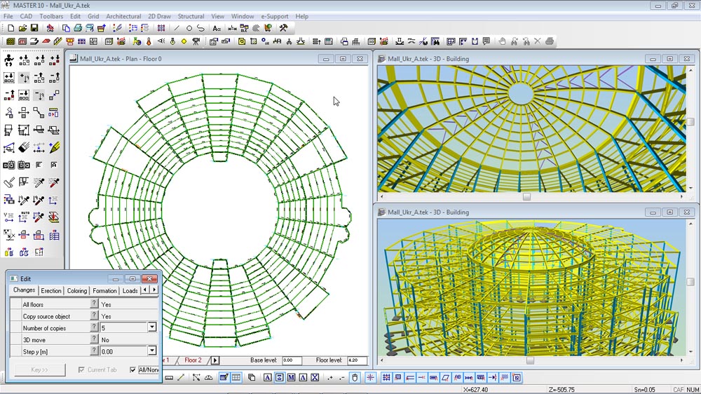
Generating tools
Generating tools facilitate the description of the structural model. Describe one floor and then generate the rest. Generate footings. Generate combinations of actions.
Not only the floor based input is supported but also a free form description is available through the «Edit» tool. Powerful commands make the construction of the complex 3D structure possible. Using this tool domes, barrel vaults, and irregularly shaped models can be described.

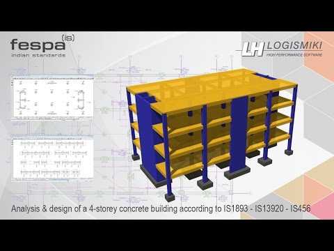
Fespa IS – Introductory video.
Fespa IS Books

Fespa IS Books