Fespa and Eurocodes
The design engineer has the ultimate control of the analysis and design procedure
Fespa fully implements Eurocodes:
- Eurocode 0
- Eurocode 2 for the design of concrete structures,
- Eurocode 3 for the design of steel structures and
- Eurocode 7 for geotechnical design
- Eurocode 8 for the earthquake resistance of structures.
By choosing the appropriate National Annex the design engineer has in their hands the best tool for designing structures with adequate resistance to earthquakes, provided in areas of medium or high seismicity (Turkey, Portugal, Spain, countries of Northern Africa, etc).
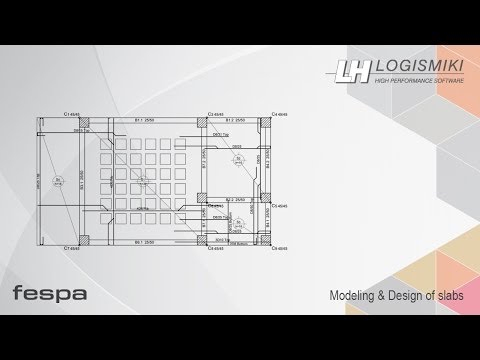
Design
The following step is the design of all structural members according to the selected standards, the material in use and the results of the analysis.
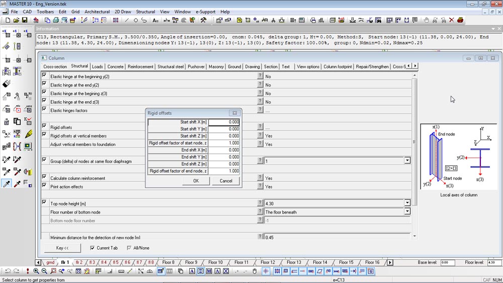
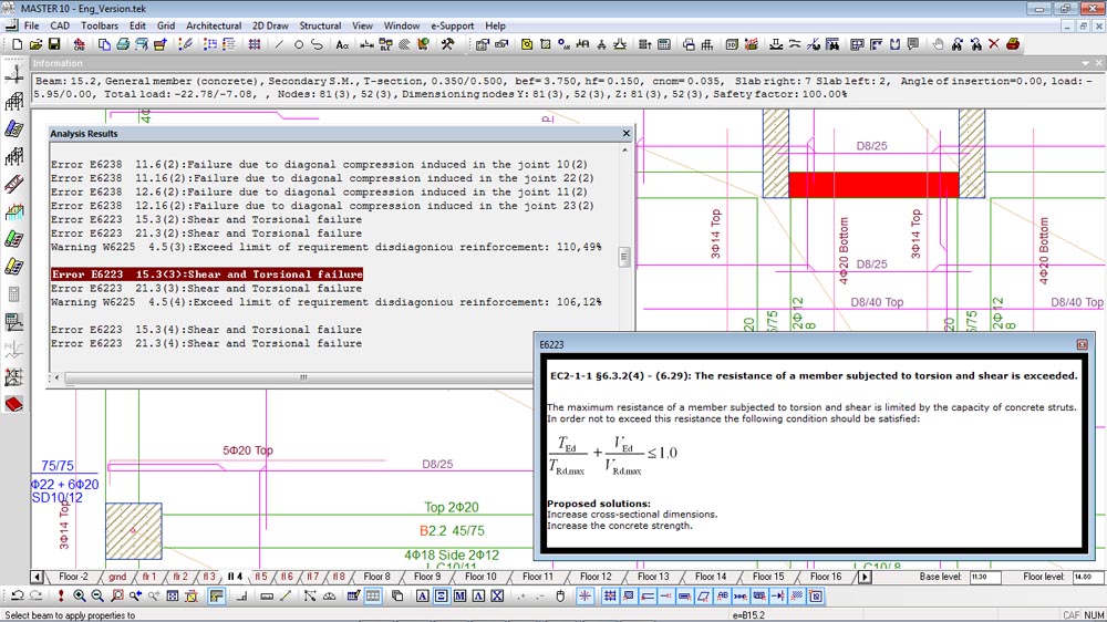
The design procedure starts automatically after the analysis. After all entities (slabs, columns, footings, beams, etc) have been checked an error record is created and is displayed on screen.
Fespa helps the design engineer to locate the members that failed during the analysis and suggests ways of resolving the error that led to the specific failure. An error or warning message appears in the results window and by double clicking on that error or warning, the relevant member (slab, column, beam and footing) is highlighted on the screen.
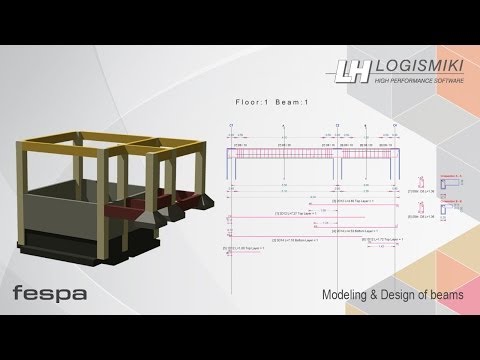
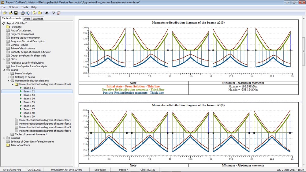
Redistribution of moments
Fespa is equipped with the moment redistribution method through which the hogging moments at beam supports are lowered leading to more uniform and economical beam reinforcement and subsequently column reinforcement.
The reduction of the additional reinforcement placed at the supports contributes in a positive way:
- In satisfying the local ductility requirement
- In applying the capacity design rule of columns in bending
- In applying the shear check of joint (DCH)
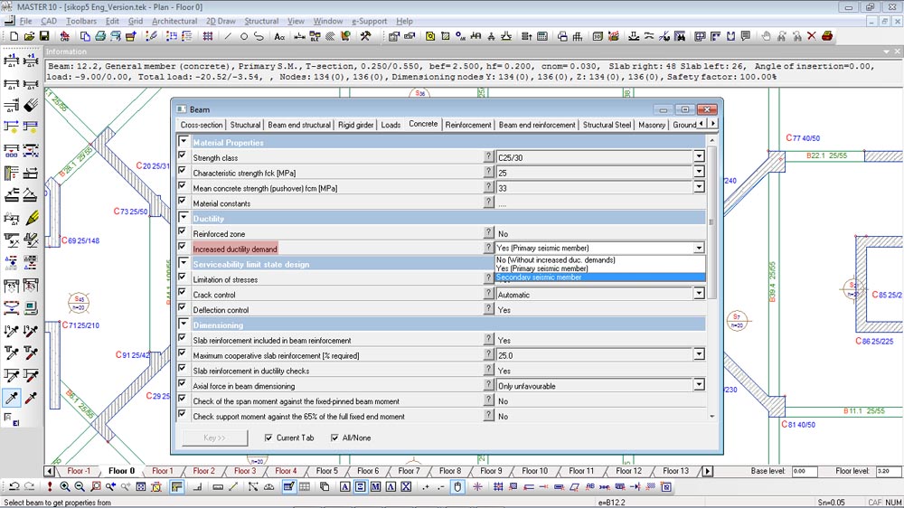
The design engineer has the option of characterising beams and columns as secondary seismic members. This option gives a way out from satisfying certain requirements of EN 1998-1.
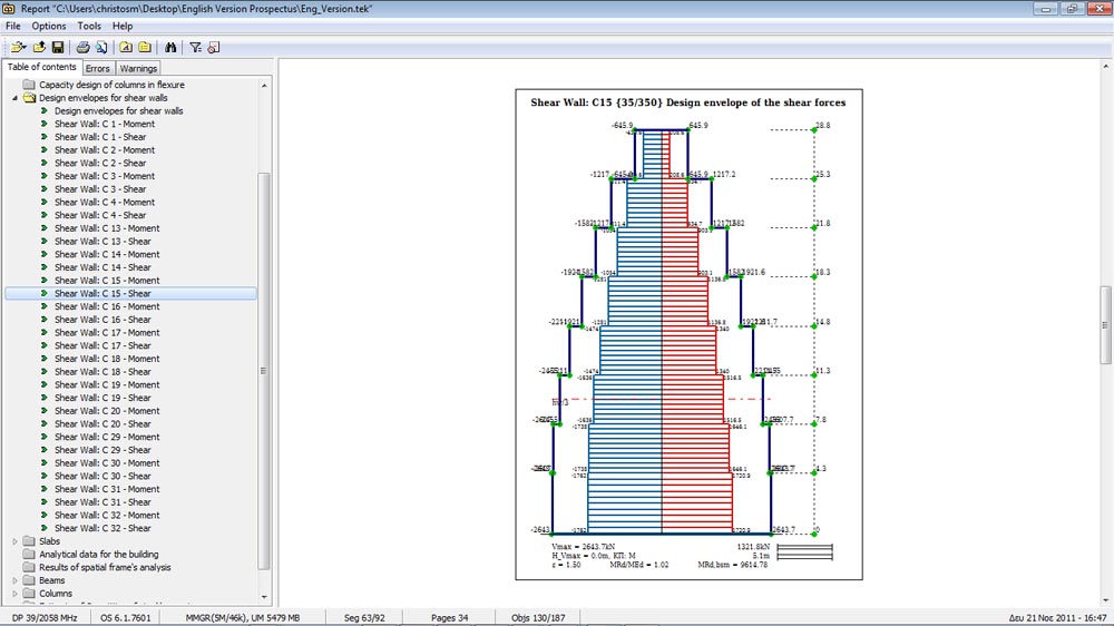
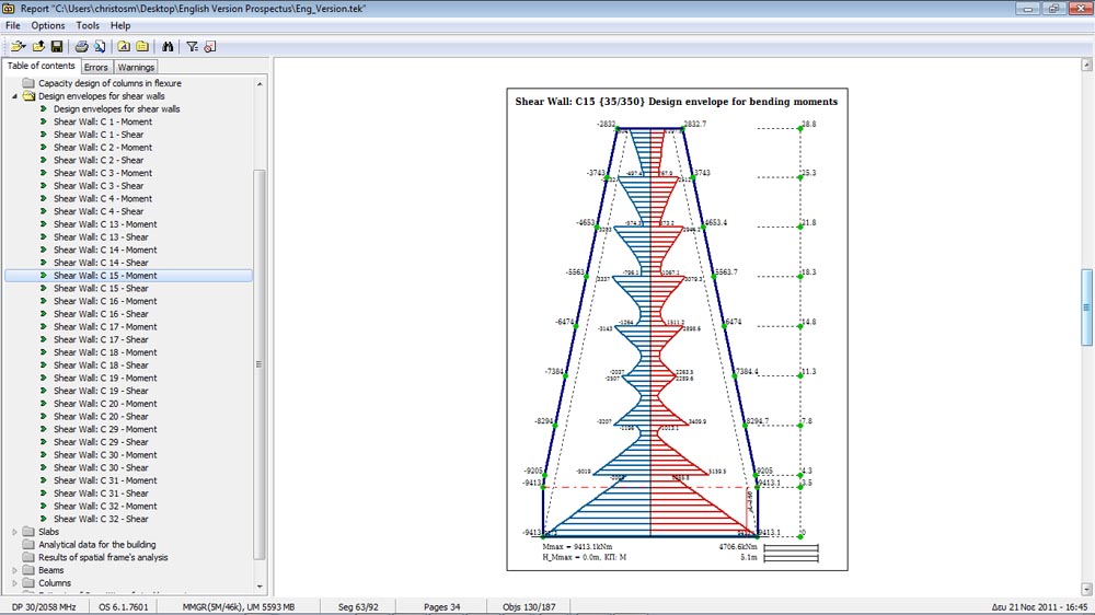
Ductile walls
Bending moment and shear force checks are performed at every level of a wall with the values that are obtained from the design envelopes which are produced in accordance with EC8-1.
Detailing for local ductility
Adequate ductility of beams is ensured by fulfilling the conditions of EN 1998-1 relevant with the maximum permissible reinforcement ratio of the tension zone and the required compression reinforcement.
Serviceability limit state controls
- Deflection control. For the deflection control of slabs there is the option of following the simplified method or of analytically calculating the deflection.
- Crack control. For the crack control there is the option of following the simplified method or of analytically calculating the crack width.
- Stress limitation. Limitation of the compressive and tensile stresses in the concrete and steel respectively is achieved, by using the appropriate arrangement of reinforcements.
Prevention of bond failure-Anchorage of reinforcement
The minimum permissible column size, to prevent bond failure, depends on the diameter of beam longitudinal rebars passing through the beam-column joint. Fespa 10 suggests minimum dimensions of column cross-sections with regard to the ductility class of the structure, the strength class of concrete, and the beam longitudinal bars passing through the beam-column joint.