Registered User
Welcome to your account
Details
New user
If you are not a registered user,
you may register here.
By giving us your permission to inform you about our products by e-mail and creating an account you get free access to:
  • New versions of LH Logismiki software
  • LH Logismiki books (Manuals, Examples, etc)
  • Tutorials


Your password must be at least 0 characters long. To make your password stronger, use upper and lower case letters, numbers, and the following symbols !@#$%^&*()

Design of steel joints

General

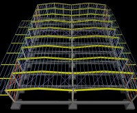
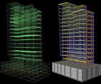
The module of Steel Connections is fully compatible with Fespa. All necessary data (member dimensions, action effects, etc) for the analysis of joints may be imported from Fespa. The results are exported in a Report accompanied by the details of every joint.

The software of steel connections may also be used independently for the calculation of the connection’s resistance. The calculation is performed based on the geometric characteristics defined by the user.

The joint is assumed to be an assembly of basic components in accordance with EC3-1-8. The calculation of the connection’s total resistance is based on plastic analysis of all the basic components that assemble the joint.

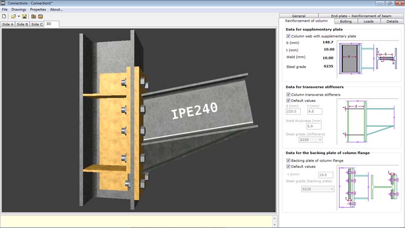
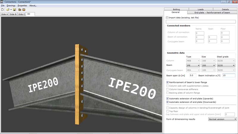
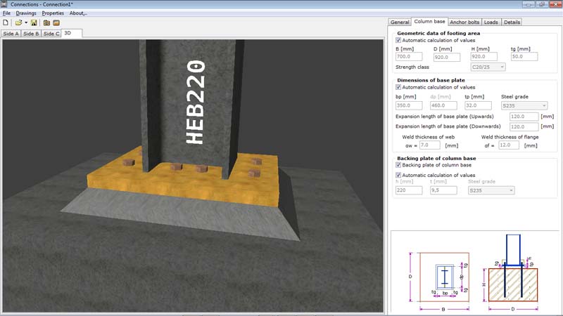
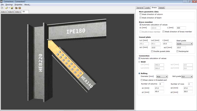
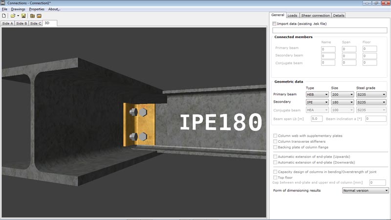
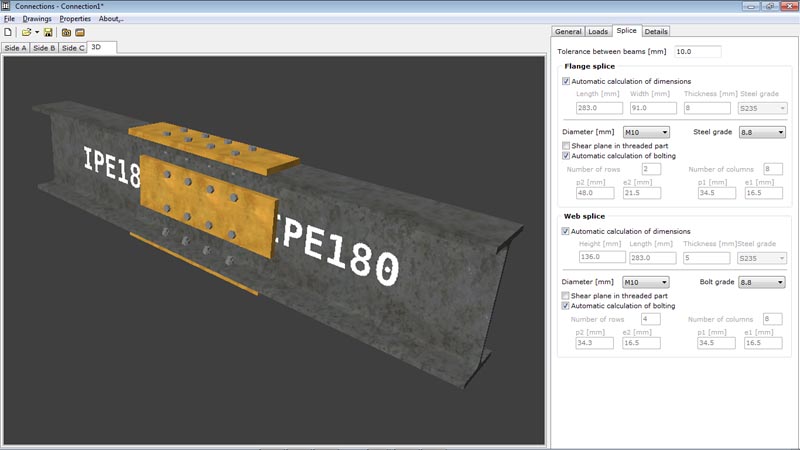
For every possible joint (beam-to beam, beam-to-column, etc) the optimum number of bolts, the best position of bolts, the appropriate thickness of the endplate, etc, are suggested.

Automatic functions for the dimensioning and strengthening of joints.

The design engineer can modify every property that takes part in the analysis.

Details of connection at any scale.

Beam-to-column moment connection with end-plate
Beam-to-beam moment connection with end-plate

Column base on foundation made of concrete (with anchor bolts)
Bolted or welded vertical bracing connection

Shear connection. Beam-to-beam. Beam-to-column flange/web
Beam splice
Beam splice

Report – Results

The results of the analysis are given in the Report, for editing or printing
1. Resistance of the joint for each load case.

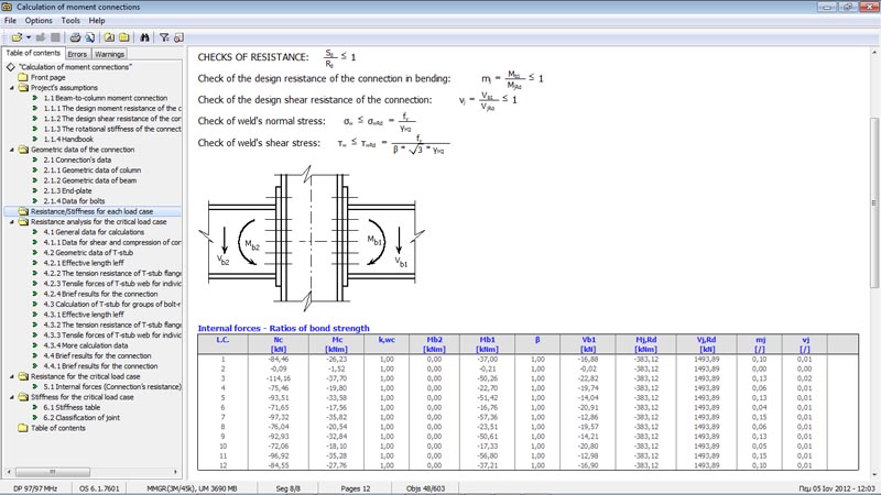
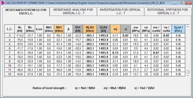
Actions, resistances of the joint and ratios of bond strength are displayed for each load case. The load case with the critical (highest) value of bond strength ratio is marked with bold font.

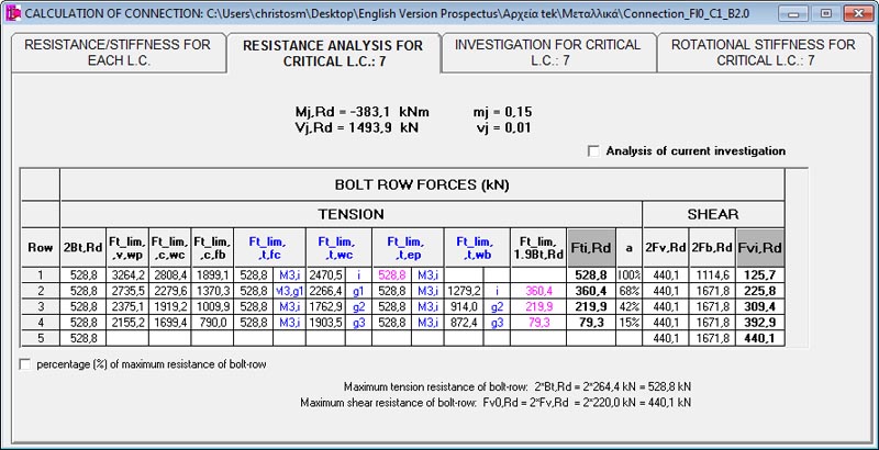
2. Resistance analysis (for critical load case).

The programme automatically calculates and displays not only the total resistance of a joint but also the individual resistances of its basic components.

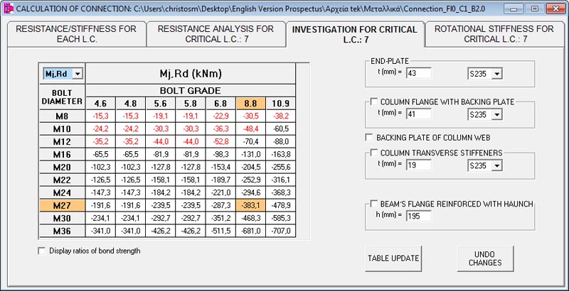
3. Resistance investigation.

All the possible values for the total resistance of bolting, for each combination of diameter and bolt grade, are

displayed in a table. The user has the option to choose the method of bolting reinforcement (supplementary plate on web, backing plate at lower flange, transverse stiffeners, etc.) and its efficiency.

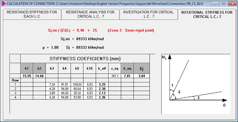
4. Rotational stiffness (for critical load case).

The rotational stiffness of a joint is determined from the flexibilities of its basic components, each represented by an elastic stiffness coefficient ki.

In case that data is imported from Fespa, in addition to the design moment and shear resistance of the joint, ratios of bond strength are calculated

The values of the design moment resistance (MjRd), for each combination of diameter and bolt grade, are displayed in the table
Classification of the joint (rigid, semi-rigid, nominally pinned)