Strengthening and repair of buildings according to EN 1998-3-Pushover analysis
General
Fespa EC is equipped with the add on module (Fespa R) which performs repair and strengthening of existing reinforced concrete buildings and evaluation of the seismic performance of a new building.
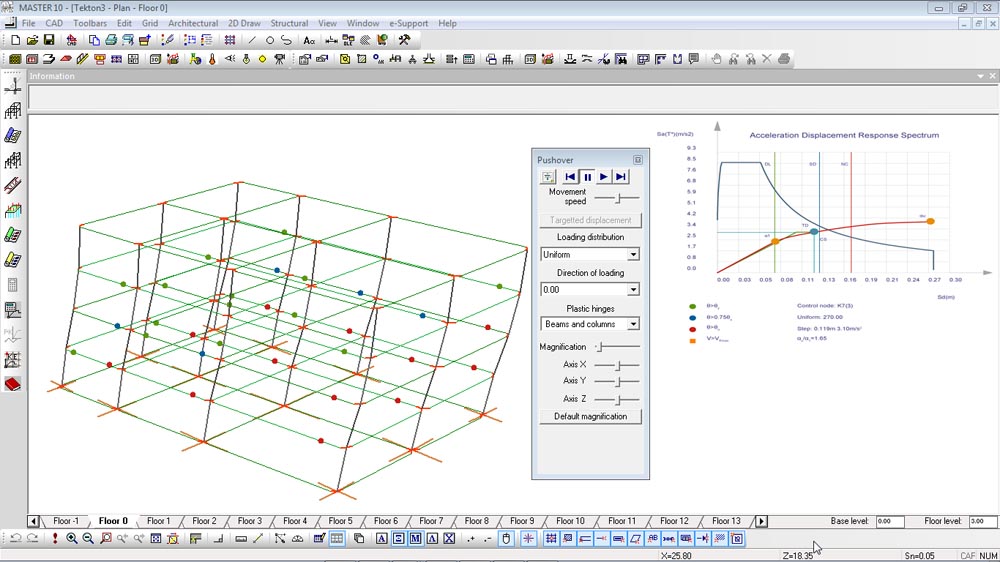
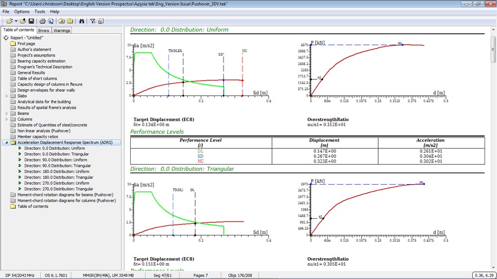
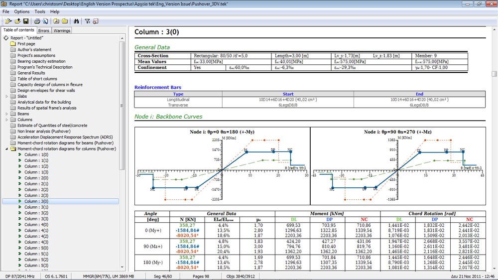
The engineer describes the reinforcement arrangement at beam and column ends of the existing building, using the relative properties and commands. Furthermore, using the appropriate set of commands and properties the user can describe column cross-sections of arbitrary shape and their reinforcement model. The moment-chord rotation diagrams of beams and columns are developed, for the assigned reinforcement arrangements (moment-chord rotation diagrams can also be developed for steel members). After the pushover analysis, the Acceleration Displacement Response Spectrum (ADRS) is generated and displayed in 3DV. The target displacement is calculated for up to three discreet accelerations and limit states. The capacity ratios, for all members, are derived for every limit state.
Static pushover analysis-ADRS
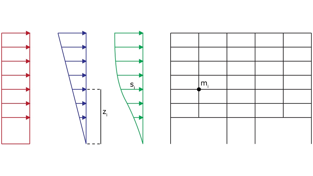
- Uniform, triangular or modal lateral load patterns.
- P-Δ effects are taken into account considering geometric nonlinearity.
- Accidental eccentricity is considered.
- The resistance curvature of the structure is developed either by applying a force method of analysis, or a displacement method of analysis.
- Acceleration Displacement Response Spectrum generated both in three dimensional wire frame view and in the Report.
- Derivation of the chord rotation angle both at yield and ultimate limit state. Moment-chord rotation diagrams for columns and beams are included in the Report.?
Assigning reinforcement model at beam ends
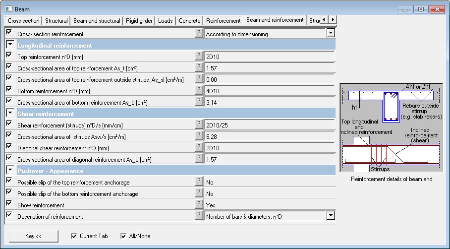
- The bending and shear reinforcements at beam end can be specified by using the relevant properties.
- The engineer has the option to characterizethe members either as new members or as existing members and either as primary or secondary seismic members so as their resistances to be calculated according to EN 1998-3.
- Slip of anchorage of bars.
- Strengthening by applying concrete jackets or by FRP plating and wrapping.
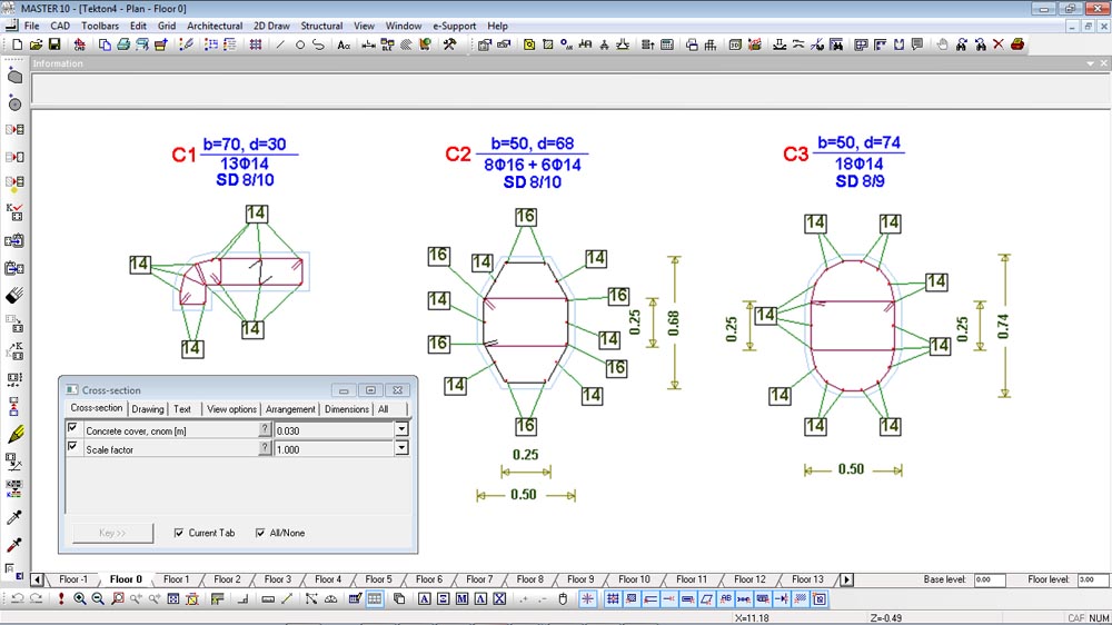
Assigning reinforcement model at columns
- Special commands allow for the description of column cross-sections even of arbitrary shape.
- The reinforcement model of the column cross-section is created by using the appropriate commands and properties.
- Taking into account the action effects derived from the analysis, the cross-section geometry, the material properties and the reinforcement model:
The safety factor against bending is calculated.
The moment-chord rotation diagrams, which will be used for the assessment of existing structures using pushover analysis, are calculated.
Pushover analysis Strengthening and repair of buildings according to EN 1998-3
Fespa EC Books